|
Web links: |
Replacing the Starter on my VolkswagenPAGE UNDER CONSTRUCTIONmain Volkswagen Beetle PageI bought the Beetle right before we moved from Illinois to Kentucky (in July 2006). I had it checked out by our mechanic in Champaign, who it turns out cut his teeth as a mechanic working on Volkswagens. He got it tuned up and ready to go for the trip. I drove it around town to get used to driving it, and I didn't have a lick of trouble the whole time. With the move coming up, I didn't have to chance to take it out on the road and test drive it, so the first time I put it into fourth gear since I test drove it before buying was when we headed east from Champaign on the way out of town to head to Kentucky to meet our stuff. Crossing the border on I-74 into Indiana, I decided that I wanted to get gas. We stopped, and fueled up...and the Beetle wouldn't start. Argh. My wife was in the non-vintage car with the cats, so she headed on to Kentucky while I stayed and dealt with my now dead prized vehicle. It was a long time to get towed to the one place in Indianapolis that would work on a classic Beetle. It wasn't the battery, but they said it was some loose wiring. Fixed it for a minimum of cost, and got me on the road. Several hours later, just north of Lexington, Kentucky, I stopped for gas. When I go to start the car...the car fails to start in exactly the same way! Double-ARRRGH! I got it push-started, and stop in a hotel for the night, figuring that I can deal with car that won't start, but I don't want to deal with it in the dark. So the Beetle made it to Kentucky, and for two months it was my primary car, including driving over a thousand miles in 80-mile installments while I was taking flying lessons. For almost two months, it started for me every time. I knew there was something lurking there, but I couldn't fix a problem that never actually happened. However, starting in September 2006 sometime, the car failed to start a couple of times at my destination. Once at flying lessons, once at a different airport. Unfortunately, there was nothing I could do at that time that would help me diagnose the problem. After I got home on one of the trips where it died, after I turned off the engine, out of habit I turned the key to see if the engine cranked. It didn't--so I finally had it at home in a state that I could try and find the problem. So here were the symptoms: When I turned the key to "on", the two warning lights (one for the generator and one for oil pressure) would come on as normal. When I turned the key to "start", the warning lights would dim slightly, but no cranking at all. (All the times it failed to start, in July on the road and the later times, all had the same effect.) When it failed in the garage at the house, and I went out the next day to try it, it still failed to start in the same way, so I had the time to track it down. The dealer in Indianapolis already figured out that it wasn't the battery; they hooked up a huge battery pack to the car, and it still wouldn't start. And the fact that the lights were dimming indicated that there was current going somewhere. Later on September, I figured out that battery voltage was definitely getting to the hot side of the starter solenoid coil, but not to the starter motor. So my conclusion was that the problem was in the starter itself; the solenoid wasn't closing. It was a mechanical problem with the starter solenoid, so for simplicitie's sake, I just decided to replace the whole starter. There was another issue with the car was the it looked to me like there was a piece of engine tin missing, the that blocks off the front part of the engine compartment. That, and the rubber lip seal all the way around the engine compartment (both horizontally and around the front) had pretty much disintegrated. To get to the front of the engine to replace the tin, I figured I was going to need to take out the fan shroud, which sort of sits up in the middle of the engine and blocks off the front part of the compartment. Having the fan shroud off would make it much easier to get at the upper right engine bolt which also secures the starter, so I figured that I could just do it all at once and be one with it. That was my first major project working on the beetle; I worked on it from September through Christmas break of 2006. Starting in 1971, the oil cooler (which is on the top of the engine block on the left side) was moved out of the main part of the fan shroud toward the front of the car. This was done to make a separate air supply to the oil cooler so that the air cooling the left engine cylinders wasn't pre-heated by the oil cooler. However, this makes the oil cooler and the fan shroud much more difficult to deal with, particularly with the engine in the car. By the way, it is possible to remove the fan shroud with the engine in the car, but you must remove the decklid and its hinges to get it out, the hinges get in the way of lifting the oil cooler up. The reason the fan shroud has to go straight up so far is that it goes around the oil cooler the oil cooler is tall and skinny.
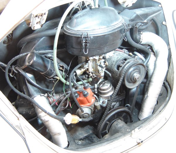
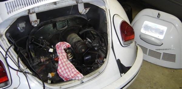
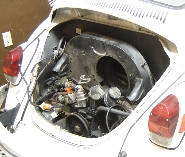
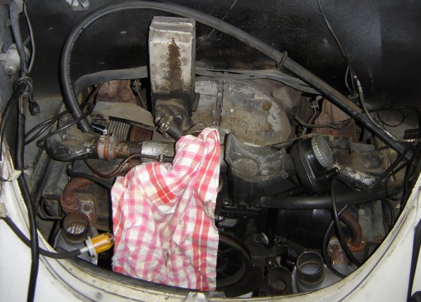
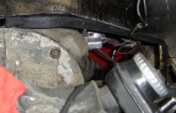
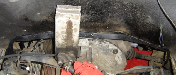
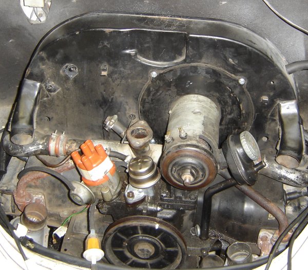
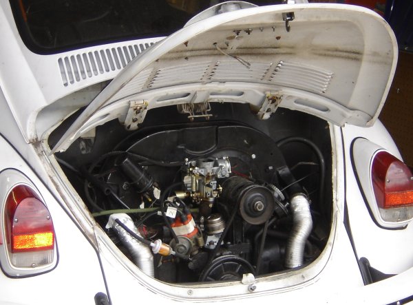
Here's the engine in September 2006 after I got sick of having to
push-start the car and before beginning dis-assembly.
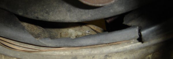
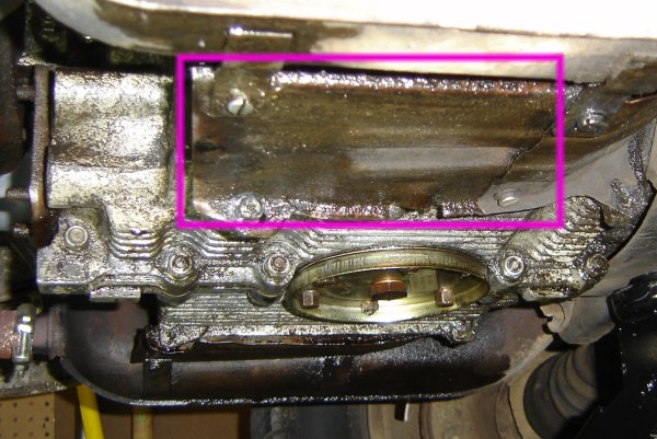
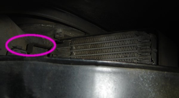
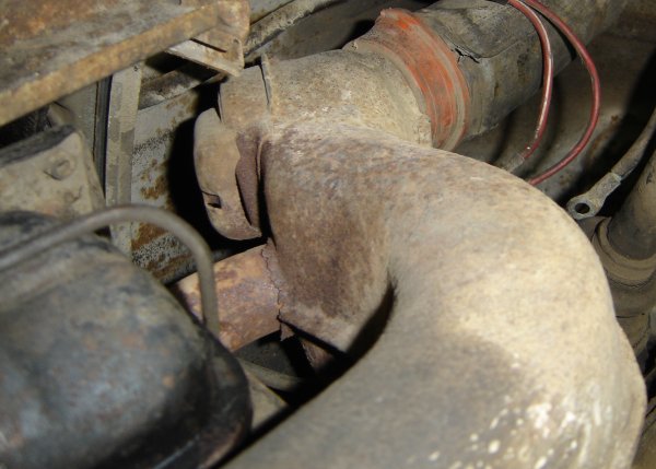
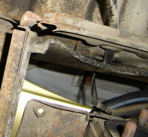
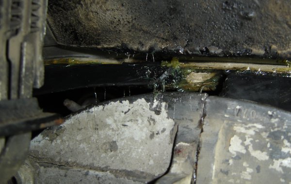
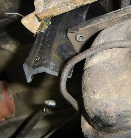
The back edge of the engine compartment. You can see that the rubber
sealing lip has hardened over time, cracked, and fallen away from the
rear engine tin.
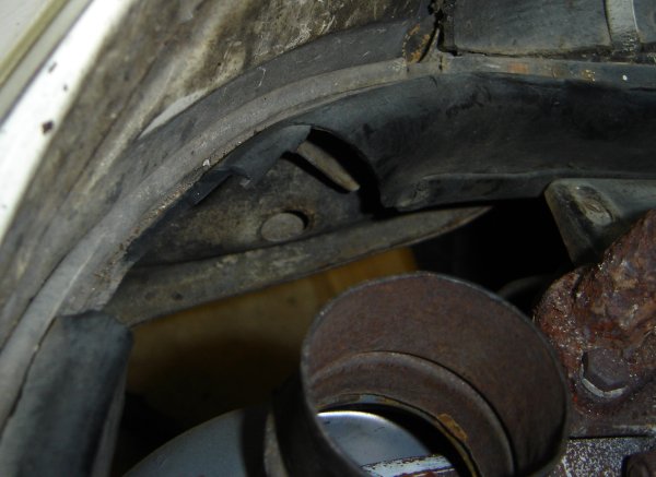
The same area after the rear engine tin has been removed.
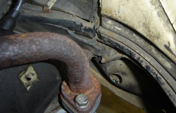
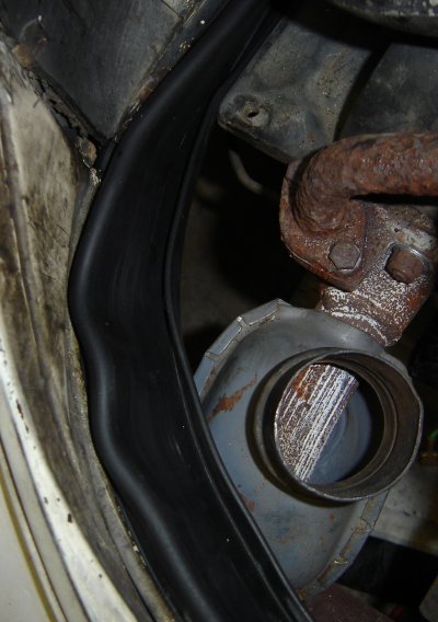
This is the remains of the rubber seal on the right side of the engine
compartment. All that's left of the rubber here is the part that sits
in the channel. It's so brittle that you can see that it's cracked
where there's a break in the channel.
In stripping down the engine, I've now removed the carburetor.
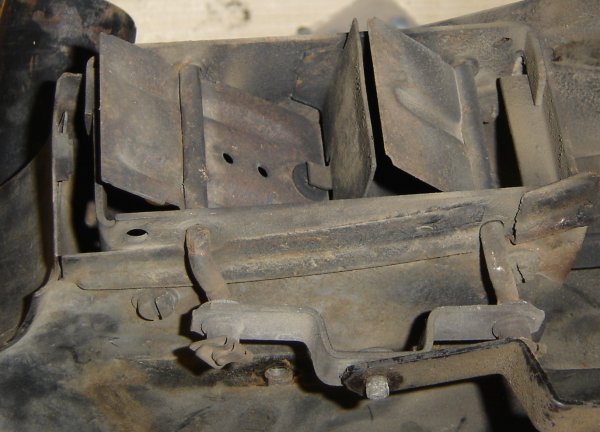
The bottom of the engine photographed from the right side. I've
highlighted the air deflector panel under the right cylinders.
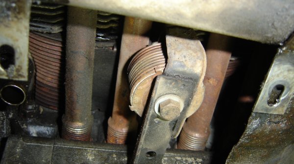
The air bellows thermostat. This thermostat is screwed onto a rod
that controls flaps at the bottom of the fan shroud. The fan shroud
cannot be removed with the thermostat attached, so we need to remove it.
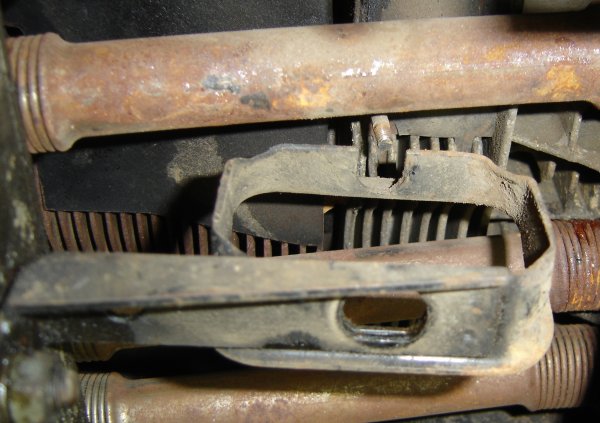
With the thermostat removed we can see its bracket better and the tip
of the rod that comes down from the fan shroud.
I've removed the deck lid from the engine compartment, but you'll
notice the hinges are still in place at the top of the engine
compartment.
The thermostat rod is free, so now we go back up to the top of the
engine compartment to continue freeing up the fan shroud. This is a
few past the upper left corner of the fan shroud into the space
between it and the back of the car. I've already removed the engine
tin that directs the exhaust air of the oil cooler, so you can see the
fins of the oil cooler on the right.
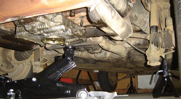
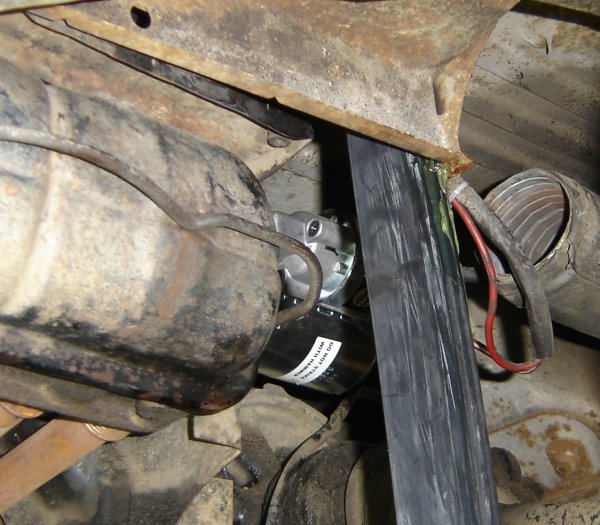
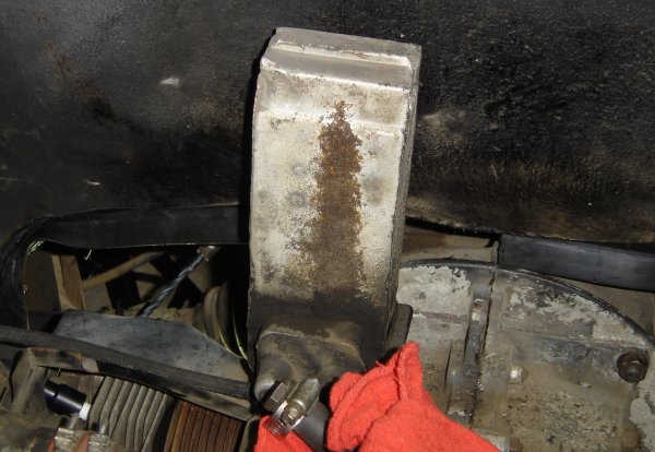
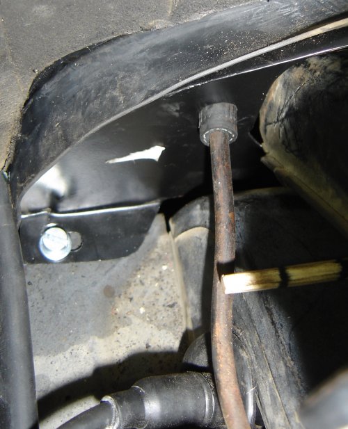
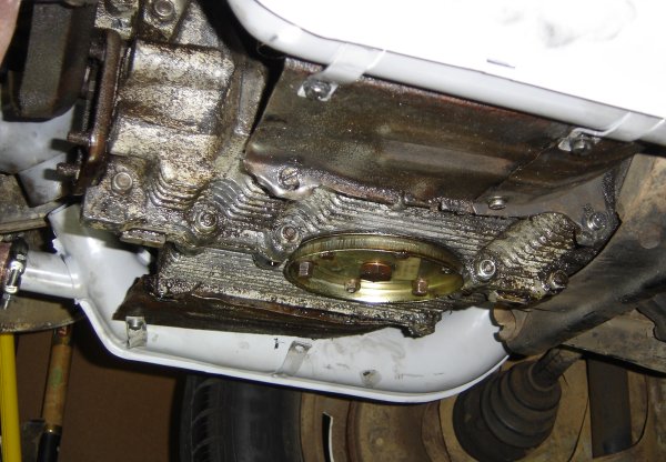
Here's the bottom of the car with the car up on stands. The jack is
point to the jacking point on the motor mount carrier.
Here, the generator has been removed from the fan shroud, and the
decklid hinges are off. The car looked like this for some time while
I figured out how to get the fan shroud off.
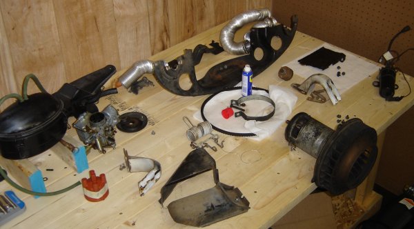
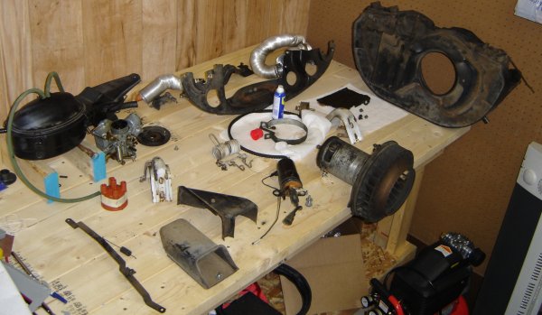
Here's my workbench as I'm taking pieces off the engine. You can see
the main rear engine tin at the top of the photo. At the very right
is the ignition coil. In the lower right is the generator with the
main engine cooling fan attached to the front.
Finally, the fan shroud is off, on the top right of the photo.
The arm that connects the left and right control vanes is the bottom
left of of the photo.
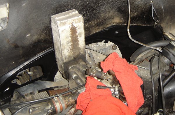
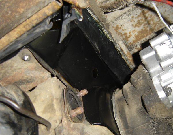
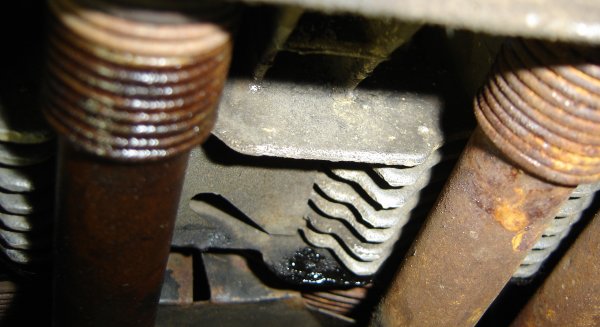
The engine compartment with the fan shroud removed. The dirty
silver-ish thing sticking up in the center of the photo is the oil
cooler. To the right of the oil cooler you can see the end of the
upper right engine mounting bolt, which also is the upper attachment
point for the starter.
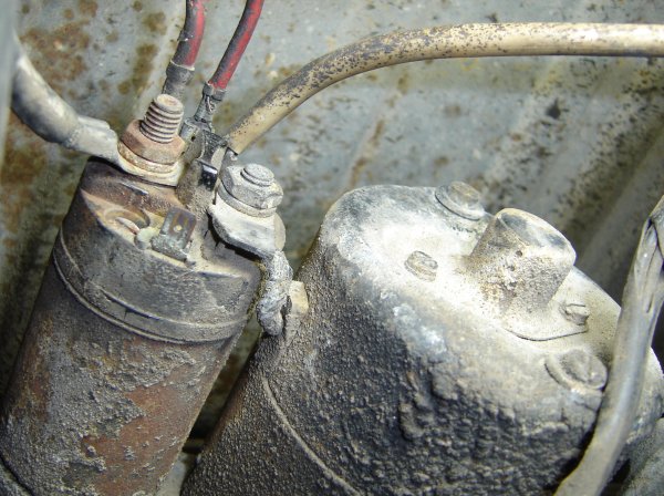
The front end of the starter. The solenoid is on the left, with the
electrical connections.
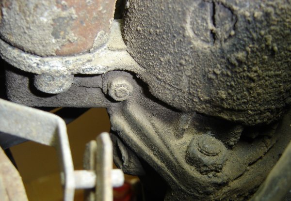
The rear end of the starter, the end near the flywheel. The nut near
the bottom of the photo is on the other (lower) mounting stud of the
starter.
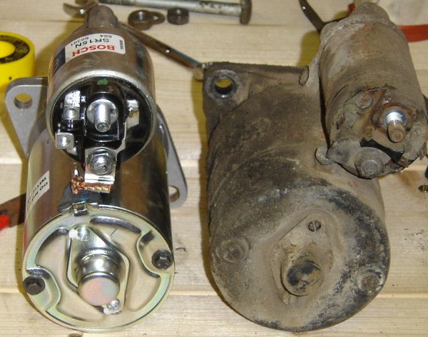
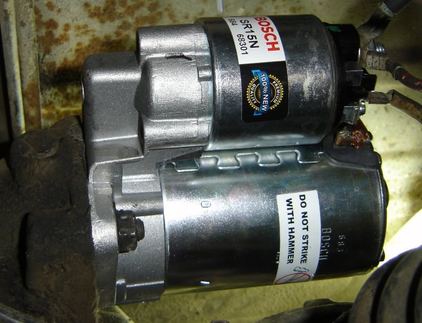
The front end of the old and new starters. The original is on the
right, the brand new Bosch starter on the left.
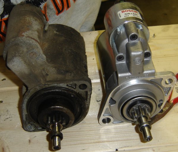
The business end of both starters. When installed, the very end of
the shaft of the starter goes into a bronze bushing that's embedded in
the body of the transmission. The gear that you see slides out to
engage the flywheel when the solenoid closes. The larger hole in the
mounting plate of each starter (lower left in this photo) is the upper
mounting hole that the engine mount bolt goes through. The smaller
hole in the starter (upper right in this photo) is the lower mounting
hole that goes over the stud at the lower part of the starter hole.
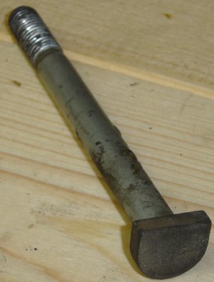
The custom upper right engine mount bolt. The head of the bolt is
shaped that way so that it doesn't turn when you tighten the nut on
the threads. The bolt goes through the hole in the starter from the
front of the car, through the transmission and engine block and the
nut goes on the threads on the rear end of the bolt.
Here's the engine compartment as I tear out the remains of the rubber
seal that goe around the upper edge of the engine compartment.
The heater box on the right side before I removed it.
The heater box removed.
Right side engine without the heater box. This is a nice view of the
right side push rod tubes.
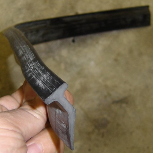
The replacement rubber lip to go around the front of the engine
compartment.
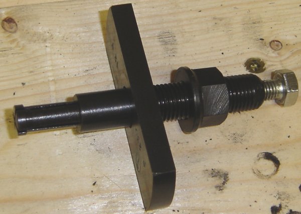
The new starter comes with the a new bushing. You must remove the old
bushing which requires this special puller. The left end of this tool
just barely fits through the bushing. When you tighten the silver
screw on the right, the left end expands to grip the edges of the
bushing, then the large nut is tightened to pull the whole thing out.
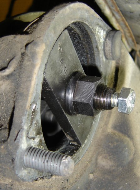
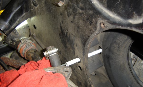
The puller installed. Below the puller is the starter mounting stud.
Above the puller is the head of the special upper right engine
mounting bolt.
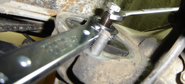
The puller attached to the bushing and ready to pull out. The long
threaded section has a flat part that the combination wrench is
attached to to keep it from rotating while the big nut is rotated. I
I bought this 19mm ratcheting box wrench to rotate the nut.
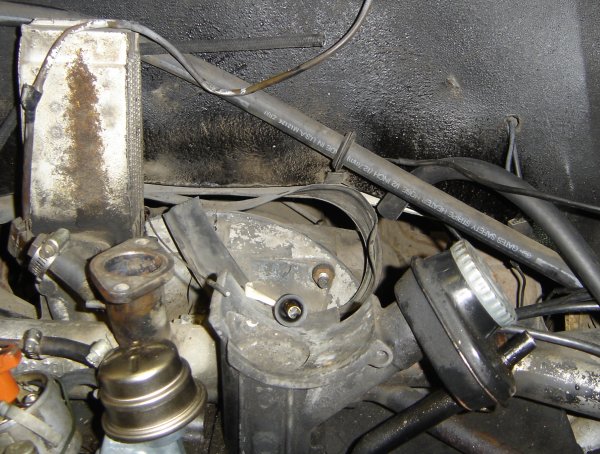
The new starter installed. I think the sign is because traditionally
of the solenoid got sticky, people would sometimes try to free it up
by hitting the starter with a hammer.
Looking up from the floor. Near the top of the photo shows the
channel where the rubber sealing lip goes.
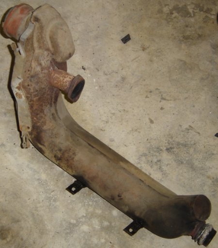
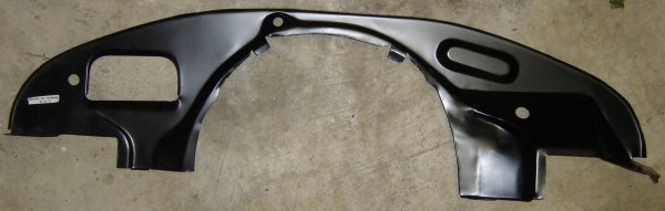
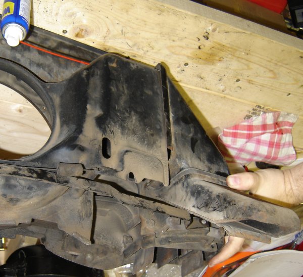
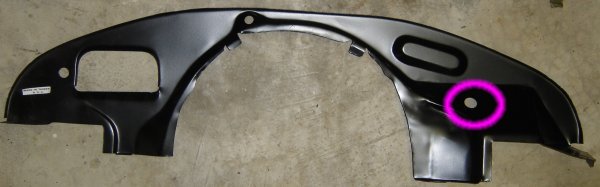
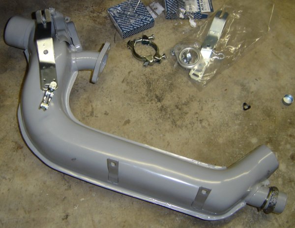
Here's the front engine tin panel that was missing from my car.
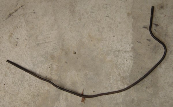
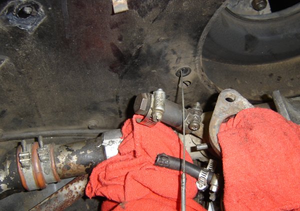
This is a metal fuel line that goes carries fuel from under the car,
through the front engine tin, around the fan shroud and then connects
to the rubber fuel line that goes to the fuel pump.
The right side of the engine compartment with the new rubber sealing
lip at the top. I only got the lip half way through the channel, to
the center line, and it was getting really hard to move. I decided it
made most sense just to stop there and feed the other half in from the
left side.
Before cutting it off, here's where I fed the slip into the channel on
the left side.
The right half of the sealing lip is in place, the left half is being
fed in from under the car. The end is behind the oil cooler here.
It's getting close, there's only a small gap.
Finally, the two halves meet.
The feed point for the rubber lip at the left side of the engine.
This is the new rubber lip installed at the back of the engine
compartment.
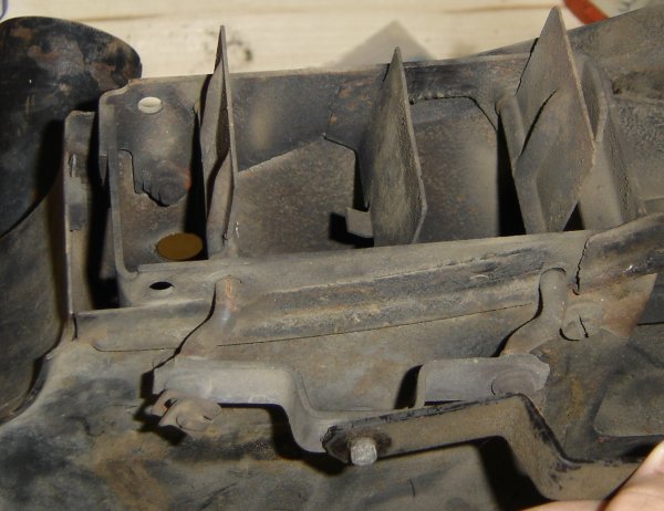
The bottom of the fan shroud sits right above the cylinders on each side of the engine. There are control vanes in the openings at the bottom of the fan shroud that close to block air from cooling the cylinders or open to allow air to cool the cylinders. The motion of the control vanes is controlled by the bellows thermostat on the bottom right part of the engine.
The fan shroud flipped upside-down on the work bench, so the control
vanes are up. Here are the control vanes closed.
The same control vanes open.
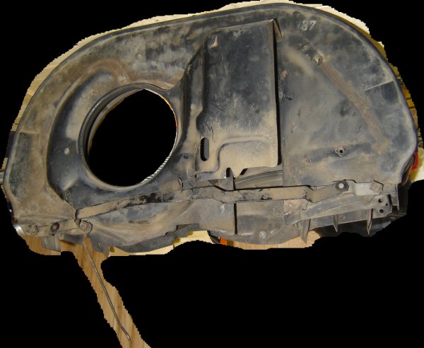
Here's the front side of the fan shroud. This is the side of the fan
shroud that you would see if you were sitting inside the car looking
back at the engine and the body was invisible. The hole on the left
is where the center of the cooling fan sticks out and collects cooling
air. To the right of the hole is the rectangular box which goes over
the oil cooler. Below the fan hole and the oil cooler box, the
air vane control arm goes across the fan shroud from left to right.
Sticking straight down from the left side of the fan shroud is the
rod that attaches to the bellows thermostat.
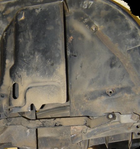
A closer view of the same part of the fan shroud. At the left is the
part where the oil cooler goes.
The box in the center of the shroud covers the oil cooler. Air passes
through the cooler from left to right. There is a passage in the
fan shroud from the fan hole (on the left in this view) to the oil
cooler. The hot air exhausts to the other side of the oil cooler and is
further deflected by two additional pieces of engine tin (not shown
here) and finally out in front of the breastplate tin. The next two
photos show those two pieces.
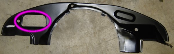
Here's the engine compartment with the breastplate tin installed.
Of the holes in the breastplate tin, the small round one on the left
is for the metal fuel line. The large rectangular one is for the oil
cooler air exhaust.
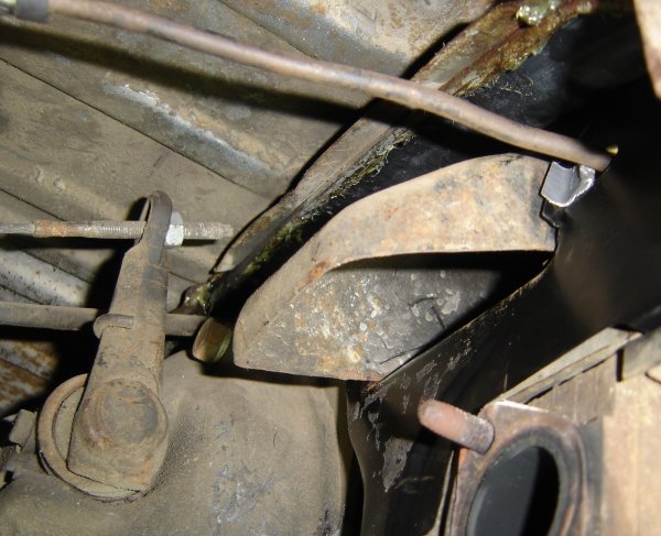
The view of the right side of the breastplate tin from under the car.
On the bottom left of the photo you can just see the front of the
right side valve cover. To the right of that is the #1 cylinder
exhaust port between the two studs. The hole for the back-up switch
from the transmission is plainly visible here.
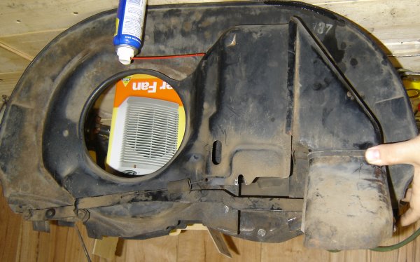
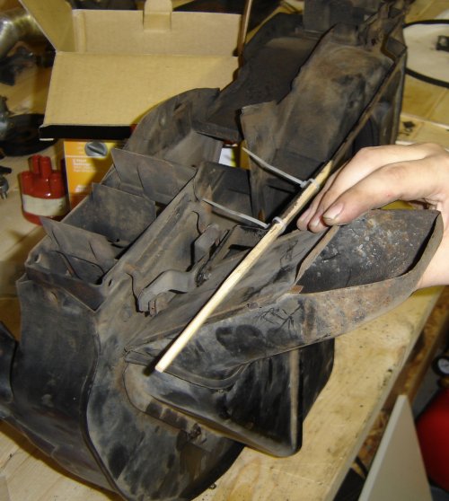
Before installing the fan shroud for the final time, I cable-tied this
stick to the bar that connects the two air control vanes in the fan
shroud. The idea was so that I can look into the engine compartment
and tell if the vanes are open or not.
The white tube is the body of a pen that I inserted into the fan
shroud to make it easier to thread the throttle cable through.
The throttle cable in place.
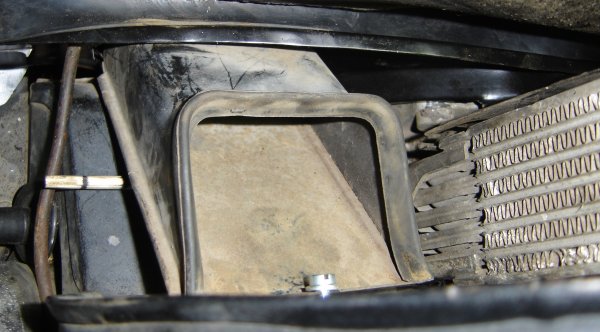
Fan shroud installed, with the lower oil cooler exhaust tube
installed, through the breastplate. The upper deflector piece hasn't
been installed yet, so the exhaust side of the oil cooler can be seen
at the right side of the photo. The control vane measuring stick is
sticking out from below the oil cooler exhaust pipe. To the left of
the oil cooler exhaust, running from top to bottom in the photo is the
metal fuel line. Below the fuel line is the #3 spark plug boot.
The right side of the breast plate tin as seen from under the car.
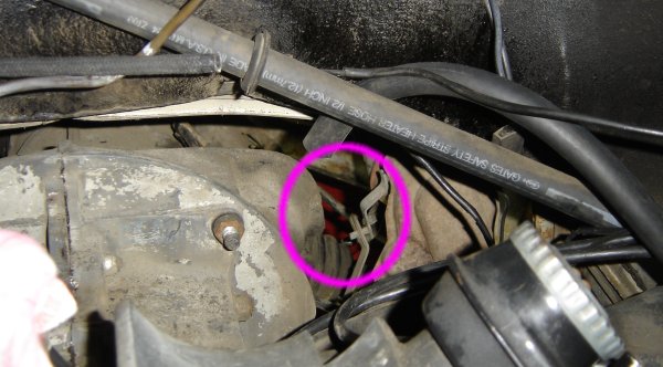
Running across the top of the photo is the metal fuel line. WARNING! This metal fuel line must be protected from
being worn by the breastplate! This photo shows a piece of duct tape
for that job, but that is certainly not a good idea. I have a much
better solution farther down the page.
Fan shroud in place, it's starting to look like an engine again.
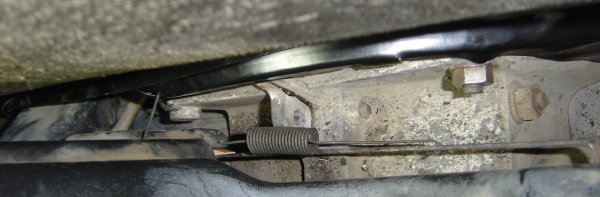
The view down the front of the fan shroud (you can't see this with the
naked eye, this is a camera-only view). In the center is the spring
that holds tension on the air control vane arm.
The right side heater box, with hardware, ready to be installed.
Looking down at the left side of the breastplate tin. Here you see
that I've put a piece of fuel tubing over the metal fuel line to
protect it from the edge of the breastplate tin.
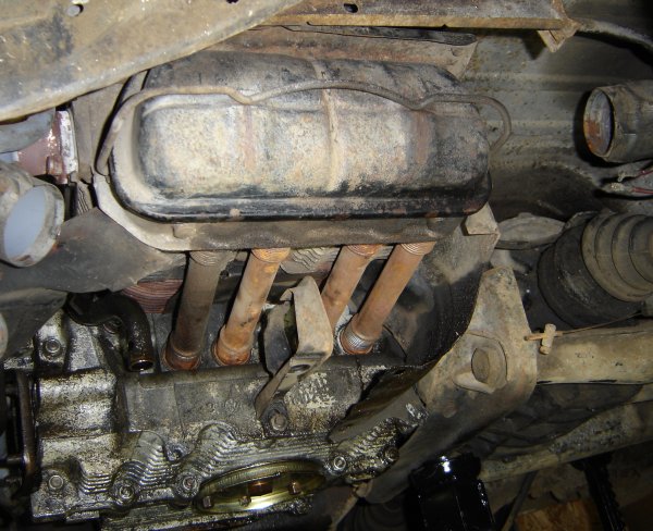
Before installing the heater boxes and the air deflectors, here's an
interesting view of the underside of the left side of the engine. The
rusty colored tubes are pushrod tubes. Interestingly, near the
center-bottom of the photo, there is a distinct oil spot on the
cylinder head fins. I suspect that this is one of the places that the
engine is leaking a little bit of oil. Probably the upper end of the
cylinder is leaking a bit against the head, and so oil drips on the
air deflector and then on down so that it's mostly impossible to
figure out where the leak is.
The underside of the engine with the new heater boxes and air
deflectors in place.
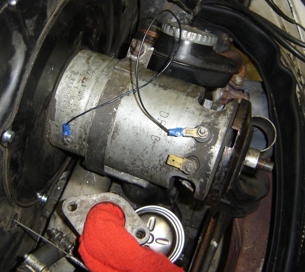
The lore is that if a generator hasn't been run in quite a while or
it's been serviced, it needs to be
polarized.
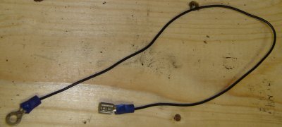
Here's the wire I made to short the field terminal of the generator.
DF terminal shorted to the generator body.
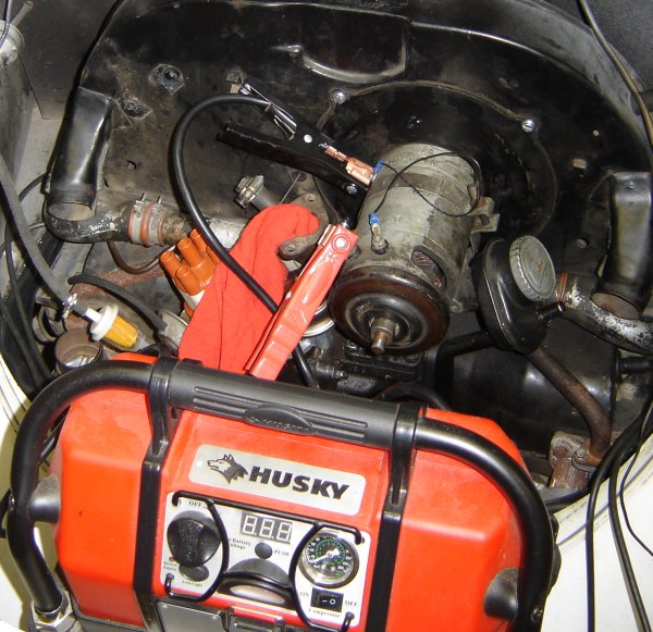
My setup for polarizing, using my emergency battery. I turned on the
battery terminals for a few seconds, which spun the generator like a
motor.
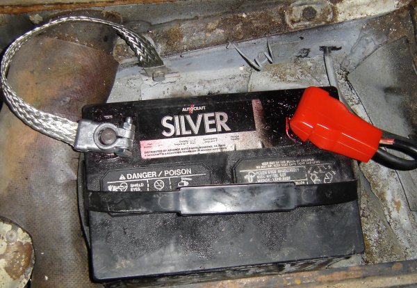
When I got the car, the negative battery terminal had a red wire going
to the frame and a black wire going to the starter. That had way too
much chance of someone connecting it backwards at some point. So I
replaced the red wire with the braided ground strap you see here at
the left.
|


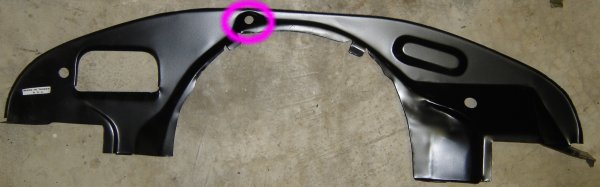
 The hole in the center, right above the engine bell is for the
throttle cable.
The hole in the center, right above the engine bell is for the
throttle cable.
 The hole on the right is for the reverse light wire to go to the
transmission.
The hole on the right is for the reverse light wire to go to the
transmission.


Home |