Site Navigation:
Craig's twitter feed:
Tweets by @gevmage
Classic Volkswagen Superbeetles (like mine) are unfortunately suseptible to a shaking front end, particularly right around 45 miles per hour. I guess the combination of very long tie rods and rubber bushings tend to generate a loose steering system.
The superbeetle has an idler arm (that is, an arm that swings in a circle wherever it's pushed) that has a bushing that wears out. The word on the street is that if this bushing is worn, it can be a major contributor to front end vibration. So you can replace the bushing with a stock one, which has rubber for shock absorption, or you can also buy a solid bronze bushing that is supposed to eliminate the vibration.
A couple of weeks ago, I ordered a bronze idler arm bushing for my car. It came yesterday, with some other stuff for the gear shifter. So I've been sorting out how to remove the idler arm bracket, remove the old bushing, put in the new one, and then put it all back together again.
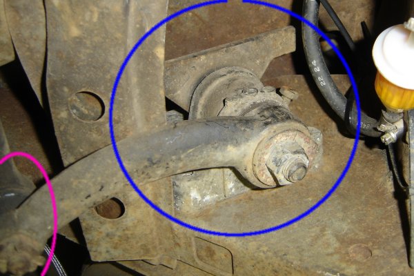
I'm going to show you where the idler arm and its bushing live. Here's an overview drawing of the front suspension and steering system on a Superbeetle, from roughly the point of view you'd have standing right in front of the left front fender:
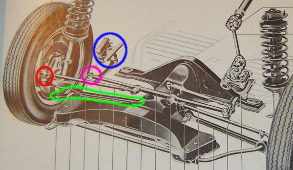
I've marked parts by circling them with color-coded lines. Blue circles the idler arm bracket. Over to the right side of the car is th steering box which contain the gears that steer the car, bu the idler just rides there. The idler arm connects to the center tie rod at the tie rod end circled in purple. The side tie rods each connect to the center of the center tie rod, and the other end attaches to the wheels at the red circle. The other major thing that connects the wheel to the central frame is the track control arm which is circled in green.
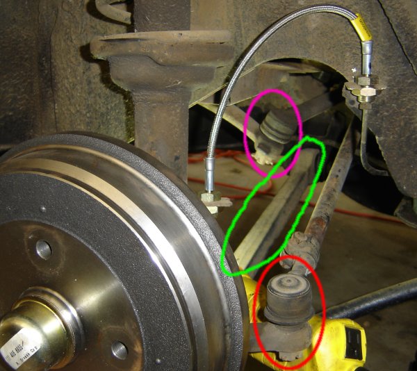
Now we've walked across the car and we're looking into the right front wheel well. Parts that are visible are circled with the same colors as before. Circled in purple is the bottom of the idler arm. The arm itself goes out of view to our left.
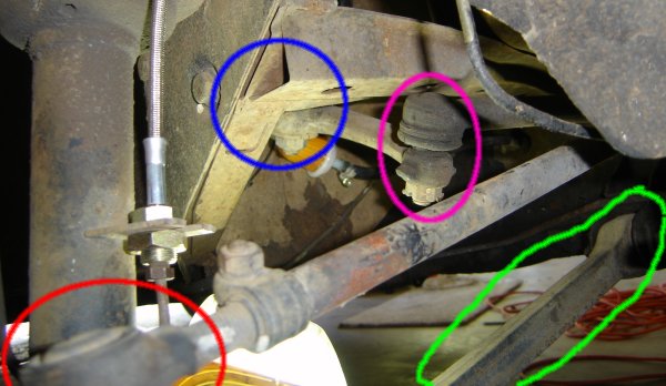
Now we've gone into the wheel well and turned a bit toward the back of the car. The idler arm bracket is obscured, but we can see the bolt where the idler arm sits on the bottom of the bracket.
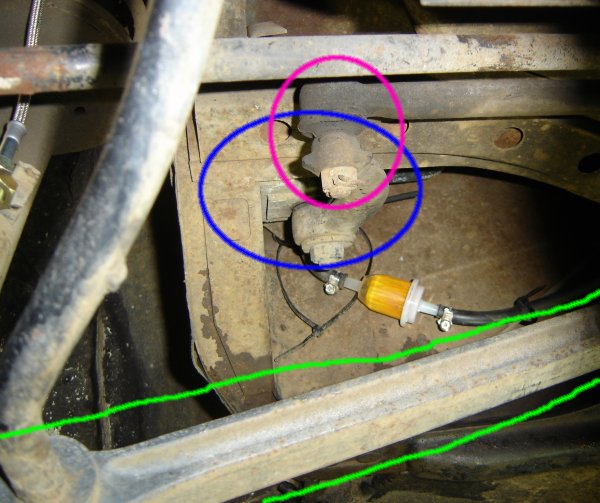
Completely under the car now. We're looking directly toward the back of the car, so the idler arm is pointing straight at us.
A camera-only shot (I try not to get my head that far under the car when it's on jack stands) looking toward the right side of the car from within the wheel well. The idler arm bracket in its natural habitat.
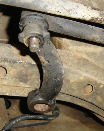
The official procedure is to remove the idler arm from the tie rod. However, this requires a special tool. However, I was able to unbolt the idler arm from the idler arm shaft and bracket, so I did that instead, leaving the idler arm hanging like this.
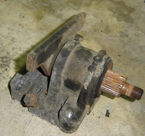
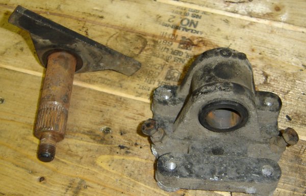
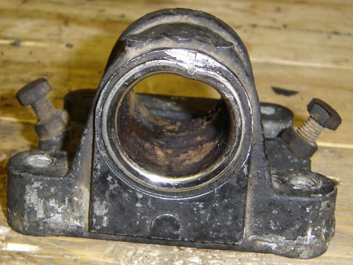
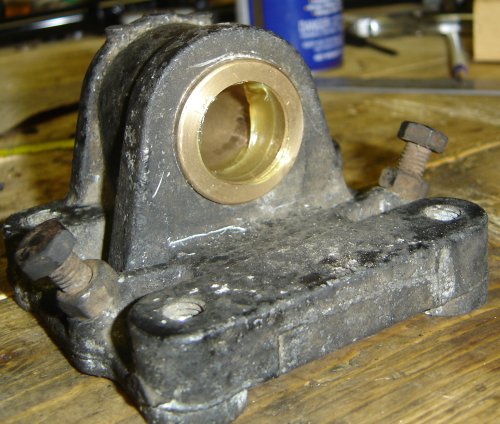
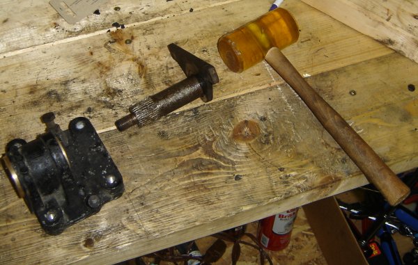
Idler arm bracket and shaft on the work bench.
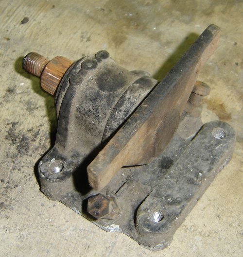
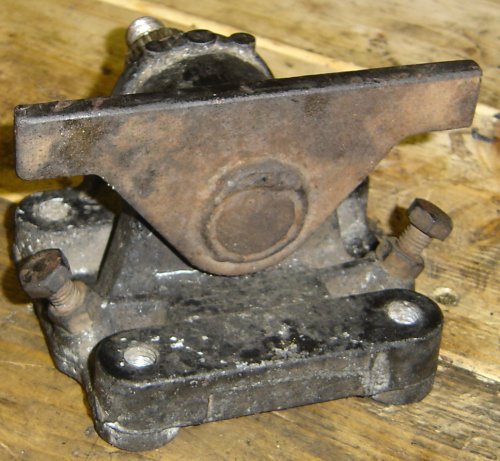
The back (top) side of the bracket. Note the two wings connected to the shaft. The two bolts you see set how far you can turn the steering wheel. When the wing hits the head of the bolt, then the steering won't go any farther.
The bushing was so loose getting it out of the bracket was easy.
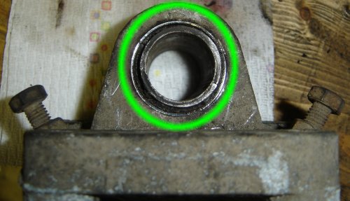
Here I've indicated the bushing that we have to replace. You can see the stock bushing's structure here. There's an outer metal sleeve, a rubber middle layer, and a metal inner sleeve.
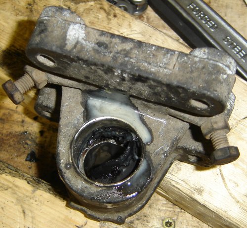
Here I'm pounding the inner sleeve out of the outer sleeve of the old bushing. The white stuff is liquid wrench. I put a bunch on the bushing before I tried to remove it. It turns out that not only does liquid wrench make things more slippery, it also dissolves rubber! After that, I used a flat punch and a hammer to pound the inner sleeve all the way out.
(By the way, the offical way of doing this job reqires a hydraulic press:
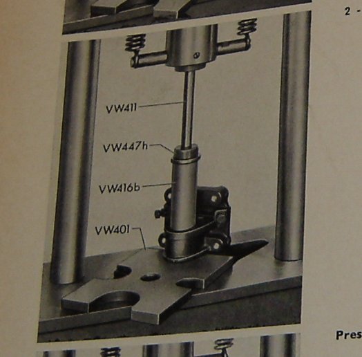
...and lots of jigs and stuff. Partially I didn't want to take the time to get a machine shop to do this, but mostly I just thought that I ought to be able to figure out a good way to do it.
The inner sleeve was easy; it's surrounded by rubber. The outer sleeve you can see here is steel and is a press fit into the Aluminum bracket. I banged on it for a while, trying to deform it enough to get it to pop out. This failed.
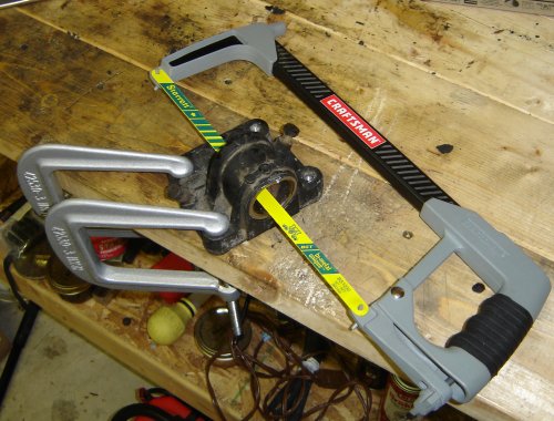
Here's my solution. I clamped the bracket to the bench and assembled the hack saw with a good, new metal cutting blade going through the middle of the old bushing. Then I just cut a slot into the bushing along its axis to weaken it enough so that I can pound it out with a hammer and punch.
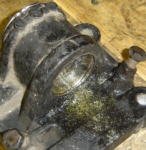
You can sort of see here the slot that I'm cutting in the bottom of the bushing.
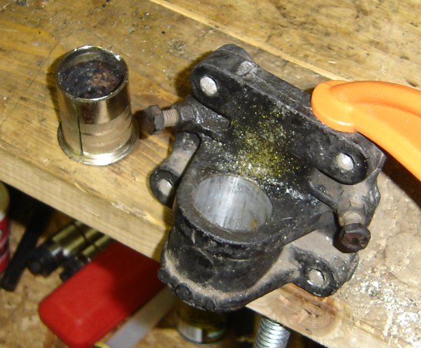
The outer bushing sleeve removed. You can see the slot that I cut in the sleeve.
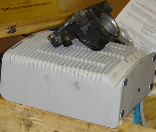
The bushings are a press fit into the idler arm bracket. To make it easier to insert, I'm heating the aluminum bracket to make the metal expand slightly and make the hole bigger.
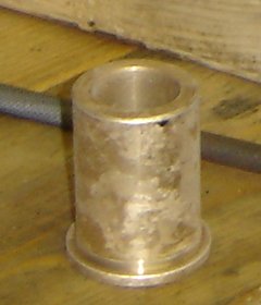
Here's the bushing fresh out of the freezer.
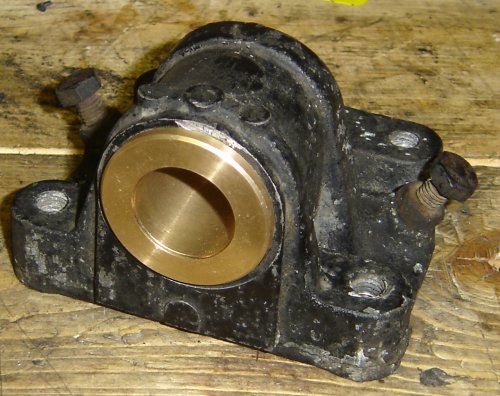
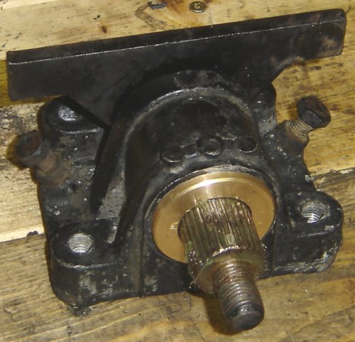
The bushing's in. Yay! When I put in this bushing, once had it started a little, I banged on it with the plastic hammer. The problem is that once the cold bronze touches the hot Aluminum, it starts to come to room temp and get bigger.
(greased for idler arm shaft)
My idler arm shaft is slightly wierd. I think it was slightly defective, in that the splined section was quite exactly lined up with the smooth section. I had a dickens of a time getting the shaft into the installed bushing. I absolutely couldn't have pushed it in. However, a few whacks with the plastic hammer got it in no problem.
Hopefully the bracket will be back in tomorrow.