The Experimental Aircraft Association in Oshkosh, Wisconsin, sponsors a series of two-day weekend workshops that each the skills for buildin Experimental Amateur-built aircraft. Before this year, I'd taken two of the weekend courses, and this January, I took a third, the avionics (Aviation Electroncs) and wiring course. The workshops travel around the country so that people in different regions can take the courses, but they always have a full set in Oshkosh at the end of January.
I drive around central Illinois a lot, driving on I-74 is pretty much
par for the course. However, when I exit onto I-39 northbound by
Bloomington, Indiana, it usually means I'm going to Wisconsin, and
more often, Oshkosh:

The last time I went to a January workshop, 3 years ago or so, the
travel up was horrid and snowy. That didn't happen this time, but
there was a dusting of snow both mornings I got up there:

Parking outside the EAA museum is always a good thing:

Here's what greeted participants at the start of the class. Yay,
wire and connectors!
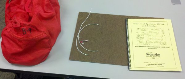
The really nice thing about a class like this is that the bag on the
left contains fairly nice tools (crimpers and such) so that you can
get used to making the connections the way they're meant to be made.
We made a wiring harness for a cockpit intercom.
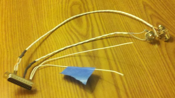
The connector at the left plugs into the back of the radio. The two
white wires at the bottom connect to power and ground. The two shielded
wires going to the two connectors at the upper right are for the
pilot's headset.
I've done lots of soldering work before, so this
part wasn't new. It was useful to learn the technique of setting up a
shielded wire. When we were finished, each of us plugged out harness
into an actual intercom to test it.
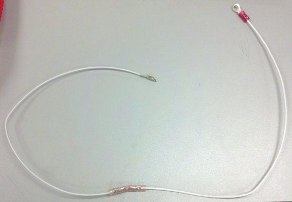
What I had NOT done before was some of the crimping techniques. A
piece of wire with some random connectors and crimps.
Also, starting with this, a piece of RG-58 cable:
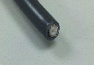
stripping it:
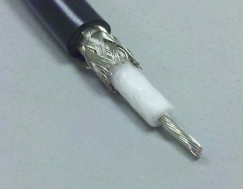
attaching the center pin:
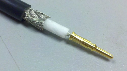
and finally ending up with a working BNC connector:
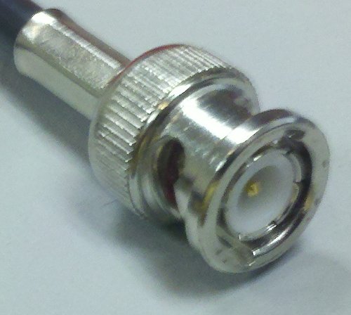
is something I'd never done before and was totally worth the cost.
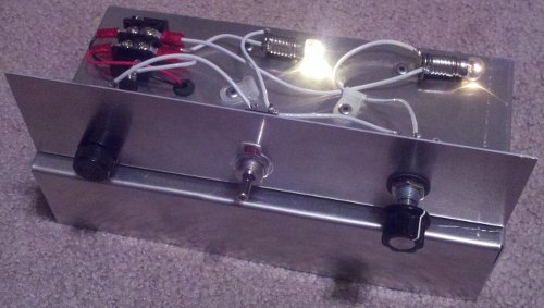
The final project was a mini electrical system.
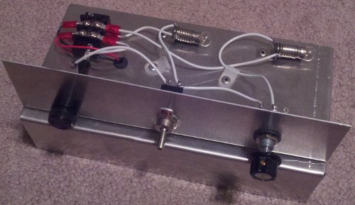
One power supply (a battery). One fuse. Two circuits, controlled by
a single switch. The black thing on the left of the panel is the fuse
holder. The thing in the middle is the switch to turn on the lighting
circuits. The light on the left is wired the same way as the
navigation lights on an airplane; on or off. The right light goes
through the rheostat (controlled by the knob on the right of the
panel) which acts like a dimmer. When you turn on the switch, the
"navigation" light comes on full brightness. The rightmost light,
which acts as an instrument panel light, comes on with them. You
control the brightness of the "instrument" light with the knob on the right.
Switch on, instrument lights at full brightness:
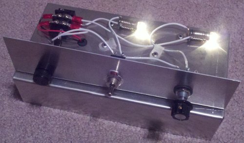
Switch still on, but instrument lights dimmed considerably:
